Pull-up resistors on digital input
On the module RobDuino we can find two “on-board push button switches”. Wiring of this switches is presented in [@fig:RobDuino_OnBoardPwshButtonSwitch_s1], where can we noticed that both switches are connected to ground voltage potential.
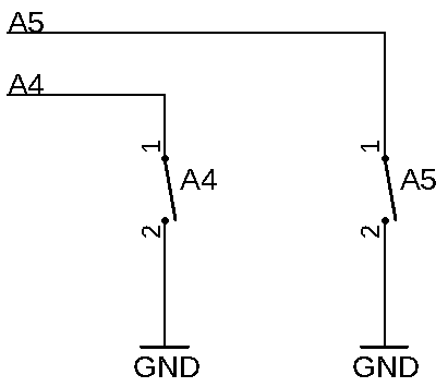 {#fig:RobDuino_OnBoardPwshButtonSwitch_s1}
To properly use this on-board push-button switches we must enable the pull-up resistors of A4 and A5 input of microcontroller.
Tasks:
- Configure pins
A4andA5as inputs withpull-upresistor. - At the end of the
setup()function add thewhile-loopwhich will delay the execution of the program until we press theA4key - acting as a “START BUTTON”. - Use the
A5key to stop the robot and terminate the execution of the program.
#include <RobotMovingFunctions.h>
const int KEY_A4 = A4;
const int KEY_A5 = A5;

void setup()
{
  setIOpins();
  pinMode(KEY_A4, INPUT_PULLUP);
  // KEY_A5 setup here...
}

void loop()
{
  moveForward();
  //to-do: the key reading
  bool stopTheRobotKey = 0;
  if (stopTheRobotKey == 1)
  {
    stopTheRobot();
    exit(0);        //terminate the program
  }
}
: Pull Up Resistors on Digital Input. {#lst:290_Pull_Up_Resistors_on_Digital_Input}
Questions:
- What is the programming instruction of reading the value form digital input?
- Which values can be assigned to
booltype variable? - Explain the programming instruction
exit(0).
Summary:
<++>
<++>
Issues:
<++>
<++>